Earthquake Source Specification
Moment Rate Function
This section describes the moment rate functions, , that can
be used in OpenSWPC by choosing the parameter stftype. In the
following, all moment rate functions have a duration (or characteristic
time) and are normalized so that the total moment is .
- Box-car function (
boxcar)
- Triangle function (
triangle)
- Herrmann function (
herrmann)
- Cosine function (
cosine)
- Küpper wavelet (
kupper)
- t-exp type function (
texp)
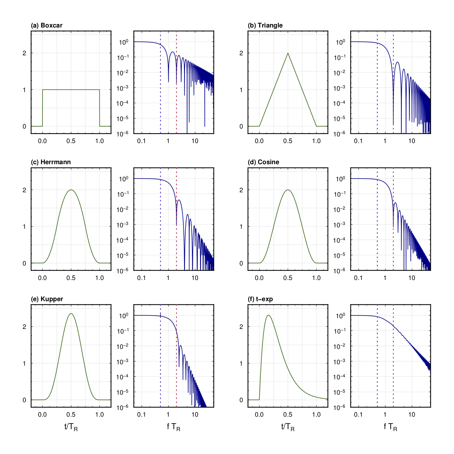
The next figure shows each moment rate function and its Fourier spectrum.
Figure
 Moment rate functions (left) and their Fourier spectra (right).
The moment rate functions have a roll off of -- at frequencies of . To avoid numerical dispersion, the source spectrum should be sufficiently small at the highest target frequency. As this maximum frequency, we adopt for all types of source time functions (the red dotted line in the figure.If the parameter is appropriately set so that numerical dispersion does not occur at frequencies below , the result should not be contaminated by numerical dispersion. In addition, the uppermost frequency, where the spectrum response of the source time function becomes flat in the frequency domain, is approximately (the blue dotted line in the figure.
Moment Tensor Source
The source mechanisms of the faulting are given by a six-component
moment tensor or by three parameters of a double couple source
(strike, dip, rake). The source locations can be given either by
their computational or geographical coordinates. The size of the earthquake can be described by seismic moment or moment magnitude or fault slip & area .
In total, there are
ten possible formats to describe the source. In the program, sources are given as a
stress-drop source by using the moment rate function. The moment rate
function is chosen from the given six functions. They require
parameters in the source list file for their starting time ,
duration , and total moment .
OpenSWPC can accept multiple point sources as multiple lines in the
source list file. There is no fixed limit to the number of sources (in
practice, this is determined by the memory size). By gradually changing
the starting time and source location, a finite fault rupture can be
mimicked. In the source list file, lines starting with # will be
ignored. By setting sdep_fit, the source depth can be changed so that
it fits the medium's velocity boundary. In this case, the depth in the
source list file will be ignored. The layer number should be specified
in the fn_grd or fn_grd_rmed list files.
Parameters
stf_format-
Format of the source list file. Choose from the following six candidates.
'xym0ij': , , , , , , , , , , ,-
'xym0dc': , , , , , , strike, dip, rake -
'llm0ij': lon, lat, , , , , , , , , , -
'llm0dc': lon, lat, , , , , strike, dip, rake -
'xymwij': , , , , , , , , , , , -
'xymwdc': , , , , , , strike, dip, rake -
'llmwij': lon, lat, , , , , , , , , , -
'llmwdc': lon, lat, , , , , strike, dip, rake -
'lldsdc': lon, lat, , , , , , strike, dip, rake -
'xydsdc': , , , , , , , strike, dip, rake -
'psmeca': lon, lat, , , , , , , , iexp (new in v5.2)
The unit of each variables are [km] for , , , [Nm] for and , [s] for and , [degree] for all parameters describing angles, [m] for slip and [m] for area .
- **
stftype** - Choice of the source time function. Select from
'boxcar','triangle','herrmann','kupper','cosine', and'texp'. - **
fn_stf** - Filename of the source list.
- **
sdep_fit** - Flag to fit the source depth to the velocity discontinuity.
'asis': do not fit (default).'bd{i}'(i=1,2,9): fits to thei-th boundary specified in the rightmost column offn_grdlst.
Specifying the magnitude of an earthquake
When the moment tensor component is given directly, there is a trade-off regarding magnitude between the specification of the seismic moment or moment magnitude and the moment tensor component. For example, the following two specifications are completely equivalent
1e15 |
1.0 |
1.0 |
1.0 |
0.0 |
0.0 |
0.0 |
|
1.0 |
1e15 |
1e15 |
1e15 |
0.0 |
0.0 |
0.0 |
Based on the input parameters, the final seismic moment is
which is determined by If more than one point source is specified, the sum of all source elements in the above equation becomes the total seismic moment; in the case of 2D P-SV and SH calculations, only the components valid for each cross section are evaluated. Because of this notation of separable magnitudes, the moment tensor component is implicitly assumed to normalized to
It is not necessary to do so, but without this standardization, the or entered as a parameter may differ from the actual calculated earthquake magnitude in the simulation.
psmeca specification
Specify the seismic source in the standard format of psmeca -Sm in GMT and globalcmt. Specify the seismic source. It specifies the latitude and longitude depth of the epicenter, the moment tensor in the polar coordinate system (in the order , , , , , ), and the exponential part (integer) of the seismic moment. Note that the exponential part is given in dyn-cm, as is customary. These parameters are converted into the moment tensor in the Cartesian coordinate system within OpenSWPC and used for the calculation. Fracture initiation time at the epicenter is , rise time is based on Ekström et al. (2012) [^Ekström2012], and scaling
which is determined by $. Again, is a value in dyn-cm.
This specification is effective from version 5.2.
Note on horizontal rotation
As of version 5.2, when the parameter phi is not equall to zero, the rotation behavior of the source mechanism is different when the source mechanism is given as strike, dip, or rake, and when it is given as moment tensor.
In the former case, the moment tensor is calculated based on the assumption that the strike were measured from the north, regardless of the value of phi. On the other hand, the moment tensor is assumed to be defined for the , coordinates after rotation. In other words, if one want to use moment tensor components from the catalog and rotate the coordinate system horizontally, one have calculate the rotated moment by yourself and give it as a parameter.
The developers are aware that these behaviors are not systematic and may be changed in future versions.
Body Force Mode
A body force source can be used instead of a moment tensor source. In this mode, the three-component force vector (, , ) should be specified. The force vector is assumed to have a bell-shaped source time function, as in the case of the moment tensor source. Although there is no restriction on the number of body force elements, it is not possible to use both a moment tensor and a body force at the same time.
Parameters
bf_mode- Flag for the body force mode. If this is
.true., the following parameters are used for the body force and the moment tensor source is ignored. stf_format-
Format of the source file. Select from
'xy'or'll'. Note that the source file format is different from that for the moment tensor.-
'xy': x, y, z, , , , , -
'll': lon, lat , z, , , , ,
-
stftype- Choice of the source time function. Same as the case with a moment tensor source.
fn_stf- Filename of the source list file.
sdep_fit- Flag to fit the source depth to a specified velocity discontinuity. Same as the case with a moment tensor source.
Plane Wave Mode
A plane wave incident from the bottom can be used as an input source
instead of the moment tensor or body force sources. In OpenSWPC, plane
wave incidence is achieved by setting the velocity vector and stress
tensor components based on the analytic solution of a plane wave
propagating upward as the initial condition.
The specification of the initial conditions includes the depth of the
initial plane wave (pw_ztop) and its characteristic length (pw_zlen;
corresponding to the wavelength), the strike and dip angle of the plane
wave (pw_strike, pw_dip), and the polarization direction (rake
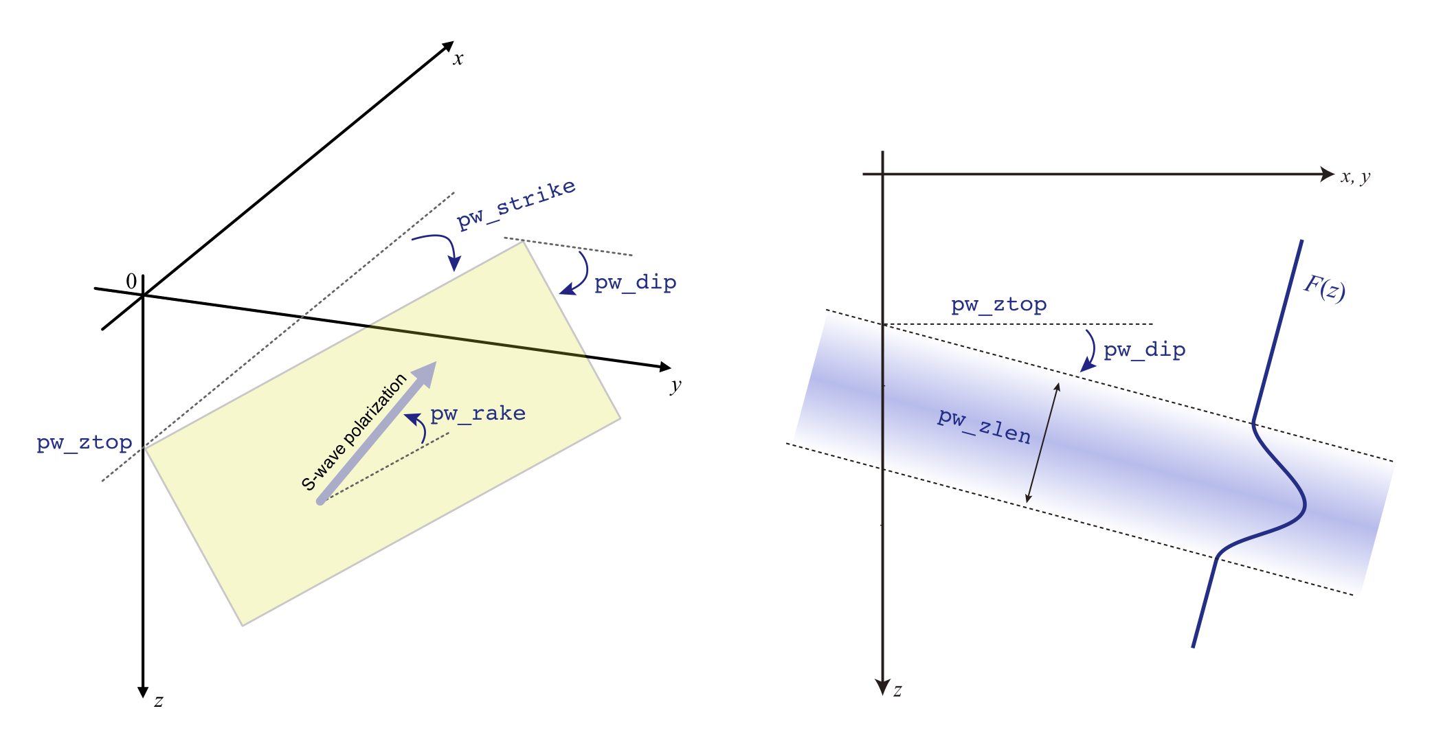
angle) in the case of an S-wave (pw_rake). See the next figure for the geometry.
Figure
 Geometry of the plane wave specification. (Left) The specification of the uppermost plane and the polarization direction. (Right) The depth cross section of the initial plane wave.
The definitions of the
strike, dip, and rake parameters follow those of the earthquake source
fault geometry of Aki and Richards (20021). For three-dimensional space,
pw_strike=0 results in the plane dip toward the -direction (east
for phi=0). A rake angle of pw_rake=0 or
pw_rake=180 will result in pure SH waves whose polarization
is parallel to the free surface.
The initial plane wave occupies a depth range of pw_zlen (km) starting
at depths of pw_ztop at the center of the horizontal coordinate.
The depth dependence of the wave amplitude is determined by the source
time functions used in the moment rate function as a function of space.
Via the definition of the source time
function, the integration of the initial plane wave along the
propagation direction will be normalized to 1.
Parameters
pw_mode- Flag to use the plane-wave mode. If it is
.true., all point-source locations (body force or moment tensor source) will be ignored. pw_ztop- -value of the top of the initial plane wave at .
pw_zlen- Characteristic spatial scale of the initial plane wave.
pw_ps- Plane wave type. Choose from
'p'or's' pw_strike- Strike direction of initial plane wave in degrees measured from the -axis.
pw_dip- Dip angle of the initial plane wave in degrees. The initial plane wave propagates vertically if this angle is zero.
pw_rake- Polarization direction of initial plane S-wave in degrees measured from the horizontal plane.
stftype- Source time function type. Same as the cases with the moment tensor or body force sources.
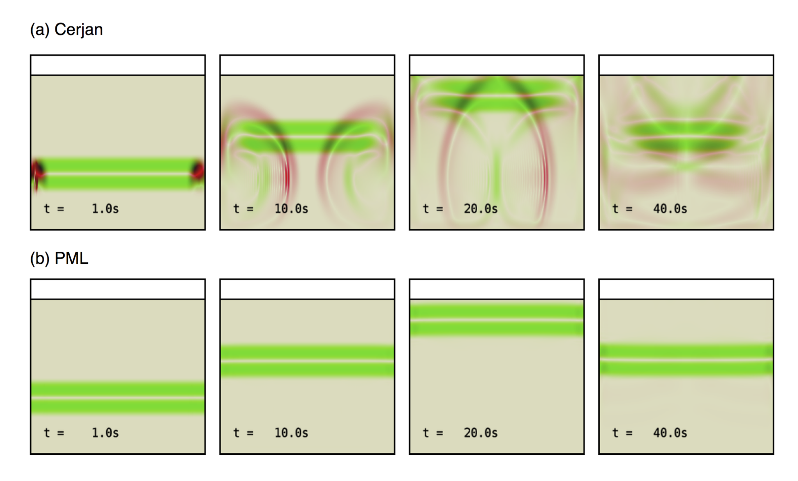
The use of the PML absorbing boundary condition (abc_type='pml'; see this section for details) is
strongly recommended for the case of plane wave incidence. The simple
Cerjan's (abc_type='cerjan') condition always causes significant
contamination by artificial reflections.
Figure
 Snapshots of the absolute values of divergence (red) and rotation
(green) for the case of vertical plane S-wave incidence with (a)
Cerjan's condition and (b) PML boundary
conditions.
Even when using the PML boundary, the tilted plane wave incidence (with
nonzero pw_dip angle) causes some amount of artificial reflections. It
is highly recommended that the boundary effect be confirmed with
snapshot visualization when using this plane wave mode.
-
Aki, K., and P. G. Richards (2002), Quantitative Seismology: Theory and Methods, 2nd eidtion ed., University Science Books. ↩